MR sensor lineup is here.
Characteristics
A sensor that uses a magnetoresistive device (MR device), and can detect magnetic field change or presence or absence of magnetic material as voltage change.
The magnetoresistive effect is the phenomenon of the electrical resistance of a solid object changing due to a magnetic field.
Output voltage change according to the distance between MR sensor and the device under test.
Unlike a magnetic head, even if the distance from MR sensor to the detected object is 0.3mm, 50% of the signal is received.
The heat properties of MR sensor resistance value
MR sensor uses a composite semiconductor InSb. That resistance value is changed by temperature and the change ratio is approx.-2%/゚C.
MR sensor output voltage heat properties
MR sensor output voltage is affected by temperature. The change ratio at close to room temperature is approx.-0.6%/゚C.
MR sensor lineup is here.
MR sensor’s operating principle
Here is an explanation in brief of what sort of output there is when MR sensor detects magnetic material like magnetic ink.
First, the resistance value of the magnetoresistive device (Below MR device) changes according to the magnetic field due to the magnetoresistive effect.
In the graph in Diagram 1 the MR device resistance value’s state changing due to the magnetic field is displayed.
The resistance value is changed by the strength of the magnetic field and is unrelated to the orientation of the magnetic field.
From MR devices with this property, devices with uniform properties (MR1,MR2) can be selected and connected in series.
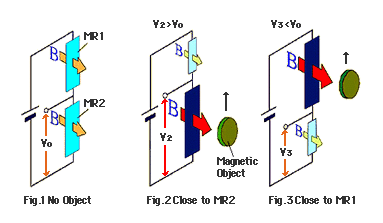
A uniform magnetic field is imposed on 2 MR devices by a magnet.
An output terminal is setup at the connection for the 2 MR devices, and the voltage at this terminal is called the output voltage.
Refer to the Diagram on the right.
When voltage V is applied to both terminals of the MR device, the output voltage becomes approx. half of voltage V.
This voltage is called the median voltage.
However, if magnetic fields of differing strength act on the 2 MR devices, the output voltage is a different value from the median voltage because the device resistance value differs.
For example, if a strong magnetic field is applied to MR 1 as in Diagram 2, because the resistance value is increased more than MR 2 the output voltage is smaller than the median voltage. Inversely if a strong magnetic field is applied to MR 2 it becomes 1/2V larger.
It can be regarded in the same way, when magnetic material is detected.
If magnetic material like a piece of iron approaches one of 2 MR devices (In this case MR 2) the line of magnetic force facing the piece of iron is polarized, and a magnetic field greater than MR 1 is applied to MR 2.
By this, the MR 2 resistance value is increased, and it is evident that the output voltage becomes larger.
Refer to diagram 3.
The following Diagram represents it sequentially.
From Fig.1 to Fig.3 shows magnetic material moving past the front surface of MR sensor.
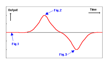
The following diagram shows how MR sensor output is changed.
It shows the output change when the magnetic material crosses the front surface of MR sensor.
As shown in the Diagram, the arrow in Fig.1~3, shows the response by the magnetic material and MR sensor in the above Diagram to the positional relationship.
Attention
Because this output voltage change method, is due to a minute amounts of magnetic material, when the magnetic material crosses 2 MR devices there are slight differences.
Here, the structure of MR sensor detecting magnetic material like magnetic ink and changing the output voltage is explained in brief.
MR sensor lineup is here.
MR sensor technical information
Reading the magnetic ink pattern
The strongest point of MR sensor application is reading magnetic printing patterns.
Magnetic printing is printing with ink blended with ferromagnetic powder, and among familiar things that are magnetic printed are the currencies of countries worldwide.
However, because the amount of magnetic material included in magnetic printing is extremely small, and a thousand yen note will not adhere to a magnet, this is not usually known.
So, how does MR sensor react to magnetic printing and detect it?
The characters shown above are an example of characters made for information processing.
These characters are stipulated in JIS X900 (E13B format).
JIS X9002 is the specifications for “the font used for reading magnetic ink characters and printing specifications”.
Of course, by these specifications when magnetically printed E13B format characters pass by MR sensor detection surface, there is a signal like in the picture in Diagram 2 in the MR sensor output terminal.
The magnetic change is extremely small, but MR sensor detects it clearly.
The circuit used is shown in Diagram 3.
However, because it is difficult to understand how the magnetic printing pattern is read, here is an easy to understand example.
Currency magnetic pattern
This time the currency is seen by MR sensor. the currency used is the US 1 dollar bill.
Because all magnetic patterns cannot be shown, the real bill (right) and the counterfeit bill (left) are connected by a diagonal line.
You can see that a signal like the printed pattern is detected.
MR sensor is used in vending machines that take currency, and by this signal it can determine if the currency is genuine or counterfeit.
MR sensor lineup is here.